es
¿Necesita ayuda ahora? ¡Llámanos!
+86-15996235291

Nuestro equipo se enorgullece de ofrecer una garantía puntual y una garantía de satisfacción del cliente del 100%.
Contacto en línea


 Inicio / Noticias / Noticias de la industria / Manual Operated Directional Control Valve vs Solenoid Valve | Reliability and Application Guide
  2026.06.13
  Noticias de la industria
 Contenido
For hydraulic system designers, equipment manufacturers, and export sourcing professionals, selecting the correct directional control valve directly impacts machine reliability, operator experience, and maintenance costs. Solenoid operated valves offer electrical actuation for automated control but require stable power supply and are vulnerable to environmental factors such as moisture, dust, and vibration. Manual Operated Directional Control Valves rely on mechanical levers for spool positioning, providing direct tactile feedback to operators and functioning reliably where electrical power is unavailable or unreliable. Understanding the differences between these valve types helps buyers select the optimal solution for applications ranging from agricultural machinery to mobile construction equipment.
Solenoid operated valves are common in stationary industrial machinery where clean, dry, temperature controlled environments and stable electrical supply are available. They enable remote control and integration with programmable logic controllers. However, in mobile equipment operating in fields, forests, or construction sites, electrical failures from moisture ingress, wiring damage, or battery depletion can disable the entire hydraulic system. Manual valves provide inherent immunity to these failure modes, with a simple lever connection that works regardless of electrical conditions. The following table summarizes the key differences between manual operated directional control valves and solenoid operated valves.
| Performance Indicator | Manual Operated Directional Control Valve | Solenoid Operated Directional Valve |
|---|---|---|
| Actuation Method | Mechanical lever direct operator control | Electrical solenoid remote or automated |
| Power Source Requirement | None no electricity needed | Stable DC or AC power supply required |
| Failure Vulnerabilities | Minimal mechanical wear only | Moisture vibration voltage spikes wiring damage |
| Operator Feedback | Direct tactile load feeling | None indirect from gauges or displays |
| Environmental Suitability | Excellent for dust mud extreme temperatures | Limited requires clean dry protected installation |
| First Cost | Lower simpler construction | Higher includes coil and electrical components |
Industry experience confirms that manual operated directional control valves provide superior reliability in harsh environments and remote locations. For equipment that must function regardless of electrical conditions, manual valve technology remains the preferred choice among hydraulic system designers and equipment operators.
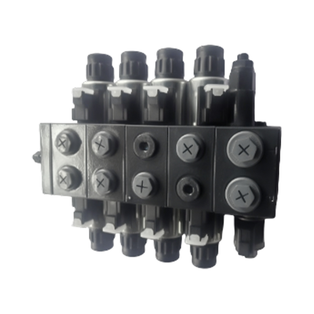
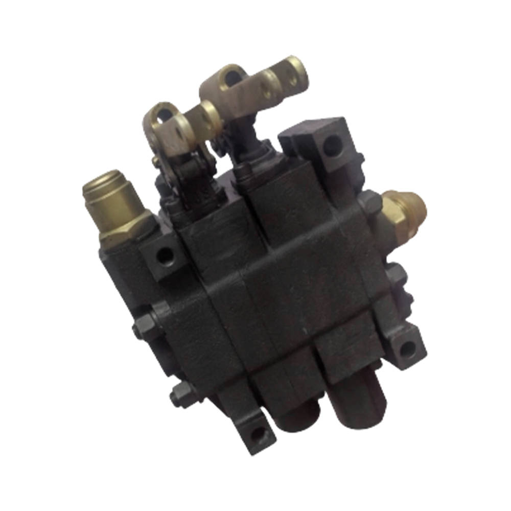
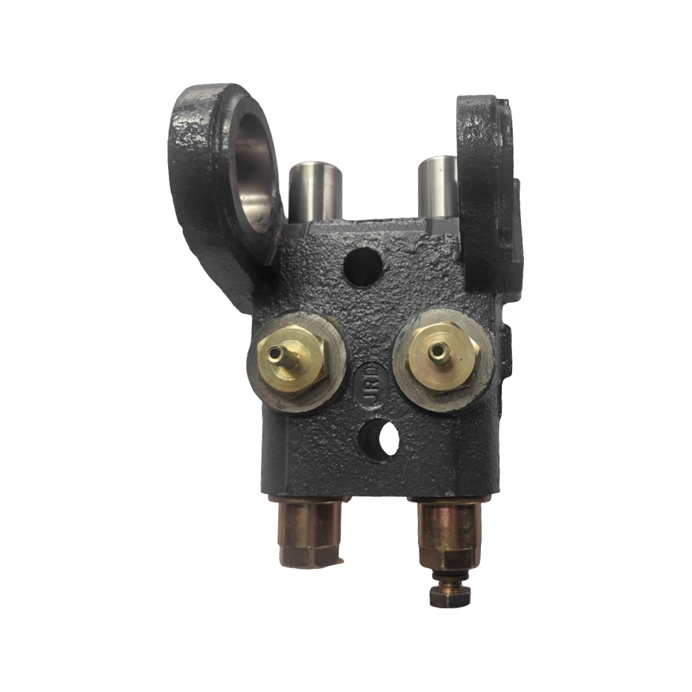
The Manual Operated Directional Control Valve consists of several key components that work together to direct hydraulic fluid flow. Understanding this construction helps buyers evaluate valve quality and select appropriate configurations for their application.
The valve body is typically made from high strength cast iron or ductile iron that withstands hydraulic pressures up to 350 bar or 5000 pounds per square inch. The body contains precision machined bores that house the spool and provide flow passages between ports. Ports are threaded or flanged for connection to hydraulic hoses or tubes. Quality valve bodies are stress relieved after casting to maintain dimensional stability over years of thermal cycling and pressure loading. Manufacturers such as Anhui Zhongjia Hydraulic Technology Co., Ltd. use modern machining centers to achieve the tight tolerances required for leak free operation.
The spool is the moving element that directs flow. It is a precision ground steel cylinder with lands and grooves that align with body ports in different positions. Spools are hardened and ground to minimize wear and maintain sealing over thousands of cycles. The spool surface finish is critical to leak free operation, with typical surface roughness requirements below 0.2 micrometers Ra. Different spool types provide different flow patterns, including open center for neutral flow to tank, closed center for load holding, and tandem center for actuator regeneration. The spool is connected to the operating lever through a linkage mechanism.
The detent mechanism holds the spool in each operating position, providing positive feel and preventing unintended movement from vibration. Spring loaded balls or rollers engage with notches on the spool or actuation mechanism. Detent force can be adjusted to suit operator preference and application requirements. For applications where the operator must hold the lever continuously, spring centered detents return the spool to neutral when released. For applications requiring sustained actuation, positive detents hold the spool in position without operator effort.
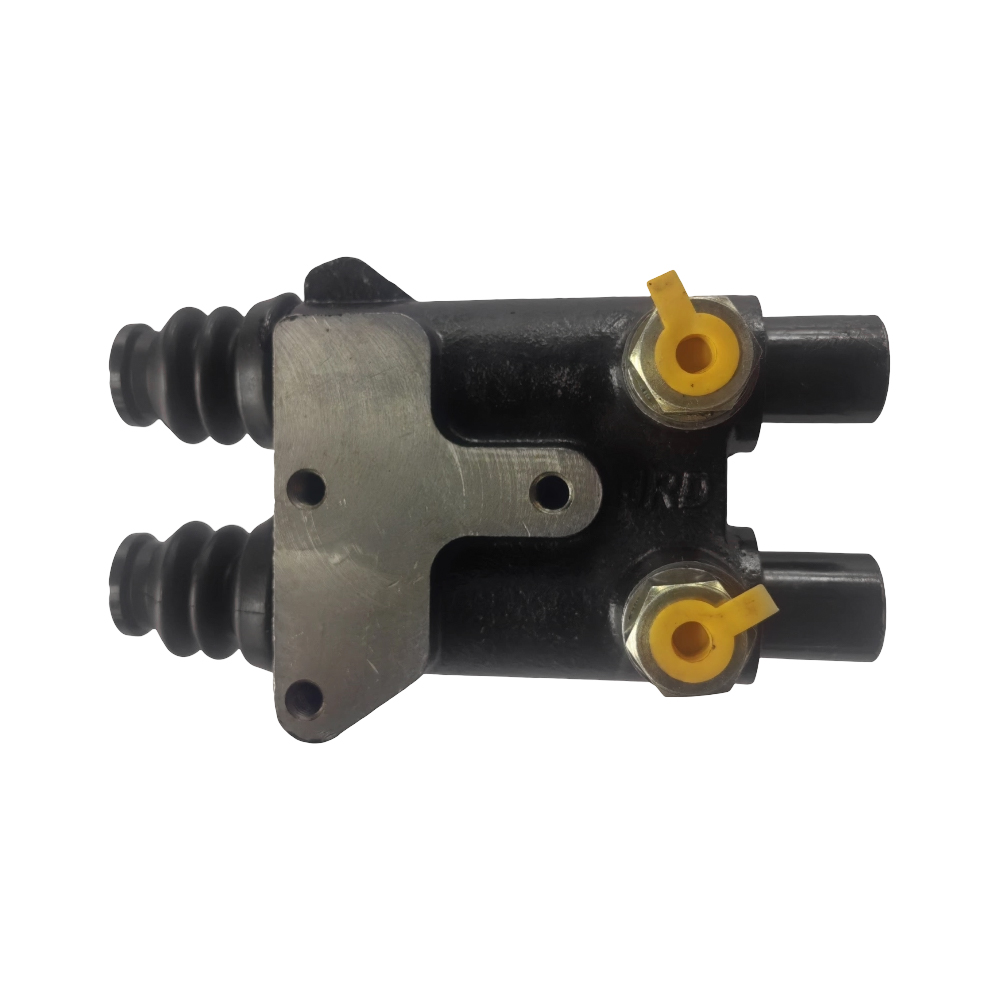
Seals prevent internal and external leakage. The spool passes through seals at the ends of the bore, preventing oil from escaping to the environment. Internal leakage between spool lands and body bore is controlled by the precision fit, typically 0.005 to 0.020 millimeter radial clearance. For high pressure applications, pressure energized seals provide zero leakage but increase operating friction. For most mobile applications, metal to metal spool to bore sealing provides the best balance of leakage control and operating smoothness.
Manual Operated Directional Control Valves are available in several configurations that determine hydraulic circuit behavior. Understanding these configurations helps buyers select the right valve for their specific machine functions and operator requirements.
Spool types determine flow paths in each spool position. The most common spool types include open center, closed center, tandem center, float center, and regenerative center. Open center spools connect all working ports to tank in neutral position, allowing pump flow to return to tank at low pressure. This is the most common configuration for open center hydraulic systems used in agricultural and construction equipment. Closed center spools block all ports in neutral, used with variable displacement pumps or accumulator circuits. Tandem center spools connect pump port to tank while blocking work ports in neutral, allowing actuator load holding while pump flow returns to tank. Float center spools connect both work ports to tank in neutral while blocking pump port, allowing the actuator to move freely under external forces. Regenerative spools connect pump pressure to both sides of a differential cylinder, extending the cylinder faster using less pump flow.
Section count refers to the number of independently controlled spools in a single valve assembly. Single section valves control one hydraulic function, such as a single lift cylinder. Two section valves control two functions, such as lift and tilt on a loader. Three, four, and five section valves control multiple functions from a single operator station. Multi section valves are constructed by stacking individual sections on a common inlet and outlet, with tie rods or through bolts holding the assembly together. This modular construction allows customization for specific machine requirements.
Inlet and outlet options include integrated relief valves, priority flow dividers, and power beyond capability. The inlet section typically contains the main system relief valve that limits maximum pressure. Optional features include load sensing capability, anti cavitation valves, and pilot operated check valves for load holding. The outlet section may include a return line filter or oil cooler connection. Power beyond capability allows the valve to supply flow to downstream valves when the spool is in neutral, essential for multi valve systems.
Lever configurations include single axis, dual axis, and cross gate arrangements. Single axis levers move in one plane, typically forward and backward for each spool. Dual axis joysticks control two spools with a single lever, providing intuitive control for loader applications. Cross gate arrangements allow the operator to move the lever to different gates for different spools, with neutral position return springs. Lever length and handle shape can be customized for ergonomic comfort and mechanical advantage.
Different industries and applications require specific Manual Operated Directional Control Valve configurations. Understanding these requirements helps buyers select the correct valve specifications for their equipment and operating conditions.
For agricultural machinery including tractors, loaders, and telehandlers, manual valves with open center spools and multiple sections are standard. Typical configurations include two to four sections controlling lift, tilt, auxiliary, and steering functions. Valves must withstand outdoor exposure to dust, mud, moisture, and temperature extremes from minus 20 to plus 50 degrees Celsius. Lever boots and weather sealed detents prevent contamination ingress. Flow rates typically range from 30 to 80 liters per minute at pressures up to 250 bar. For the agricultural market, valve reliability during planting and harvest seasons is critical because downtime during these periods causes significant crop loss.
For construction machinery including backhoes, skid steers, and mini excavators, manual valves must withstand severe vibration and shock loading. Valve bodies are typically cast iron with reinforced mounting flanges. Spools are hardened for wear resistance against contamination that may enter despite filtration. Flow rates range from 50 to 150 liters per minute at pressures up to 300 bar. For excavator applications, pilot operated manual valves provide low lever effort for precise control of digging functions. For loader applications, joystick control with dual axis levers improves operator productivity by allowing simultaneous lift and tilt control with one hand.
For material handling equipment including forklifts, pallet jacks, and scissor lifts, manual valves prioritize load holding safety and smooth metering. Integrated pilot operated check valves prevent load drift when the spool is in neutral. Metering notches on the spool lands provide fine control of cylinder speed near neutral, essential for precise positioning of suspended loads. Flow rates typically range from 15 to 40 liters per minute at pressures up to 200 bar. For forklift applications, three section valves controlling lift, tilt, and sideshift are common. For scissor lifts, valves with emergency lowering capability provide safety during power failure.
For forestry and logging equipment including knuckleboom loaders and delimbers, manual valves must operate reliably in cold, wet, dirty conditions. Valve bodies are often zinc plated or painted for corrosion resistance. Lever boots and sealed detent covers prevent moisture ingress that could freeze and block detent operation in freezing conditions. Flow rates range from 50 to 120 liters per minute at pressures up to 280 bar. For remote logging operations where electrical power is unavailable, manual valves provide the only practical control solution because solenoid valves would require batteries and alternators that are difficult to maintain in remote locations.
Properly sizing a Manual Operated Directional Control Valve requires matching flow capacity and pressure rating to the hydraulic system's pump output and cylinder requirements. Undersized valves cause pressure drop, heat generation, and reduced actuator speed. Oversized valves waste cost and space without providing benefit.
Flow capacity is typically rated at a specified pressure drop, such as 50 liters per minute at 5 bar pressure drop. The pressure drop across the valve increases with flow squared, so doubling flow quadruples pressure drop. For efficient system operation, total pressure drop from pump to tank should not exceed 10 to 15 percent of system pressure. For a 200 bar system, this allows 20 to 30 bar total pressure drop across all valves, fittings, and hoses. When selecting a manual valve, calculate the maximum flow required for the fastest cylinder or motor, then select a valve with rated flow at least 20 percent higher to allow margin.
Pressure rating must exceed the maximum system pressure including pressure spikes. Manual directional control valves are typically rated for continuous pressure of 250 to 350 bar and peak pressure of 400 to 500 bar. For agricultural applications, 250 bar continuous rating is usually sufficient. For construction and mining applications, 350 bar or higher rating is required. The valve's pressure rating includes all components including body, spool, seals, and detent mechanism. When replacing an existing valve, match or exceed the original pressure rating to ensure safety and durability.
Pressure drop characteristics vary by spool type and valve size. Open center valves in neutral position typically have pressure drop of 3 to 10 bar at rated flow, representing energy loss when the system is idling. For fuel efficient machinery, lower neutral pressure drop is desirable. When the spool is shifted, pressure drop from pump port to work port and from work port to tank port both contribute to total loss. Higher quality valves with optimized flow passages have lower pressure drop, reducing heat generation and improving actuator speed. Request pressure drop curves from the manufacturer when comparing valve efficiency.
Flow forces act on the spool as fluid moves through the valve, tending to close the spool from the shifted position. At high flows, flow forces can exceed the operator's ability to hold the lever in position, causing the spool to drift back toward neutral. Manual valves with larger spools and optimized flow passages have lower flow forces for a given flow rate. For high flow applications above 100 liters per minute, consider valves with pilot operated or hydraulic assisted levers that reduce operator effort.
Proper installation and maintenance of Manual Operated Directional Control Valves ensures long service life and reliable operation. Following established best practices helps equipment owners minimize downtime and repair costs.
Mounting location should provide operator access to levers without reaching across moving parts or hot surfaces. The valve should be mounted with ports oriented to minimize hose bends and lengths. Vertical mounting with work ports on top and inlet outlet on the bottom is preferred to prevent contamination settling in spool bores. Use isolation mounts if vibration levels are high to prevent mechanical stress on the valve body. For outdoor equipment, locate the valve under a cover or shield to prevent direct rain and sun exposure that degrades lever boots and seals over time.
Hydraulic connections must be clean and properly torqued. Before connecting hoses, verify that all fittings are free from plastic caps, metal chips, and other debris that could enter the valve and damage the spool or seats. Use thread sealant on tapered threads, being careful not to allow excess sealant to enter the valve. For O ring face seal fittings, tighten to manufacturer specifications. For flange connections, tighten bolts in a crossing pattern to uniform torque. After installation, cycle the valve through all positions while checking for external leaks.
Routine maintenance includes visual inspection of lever boots for cracks or damage that could allow contamination ingress. Replace damaged boots immediately because abrasive dust entering the spool bore will accelerate wear. Check detent operation regularly; the spool should click positively into each position and should not drift out of detent under machine vibration. Lubricate lever pivot points annually with general purpose grease. For valves without lever boots, apply thin oil to the spool ends every 500 operating hours to prevent corrosion and maintain smooth operation.
Troubleshooting common problems begins with verifying hydraulic system basics. If the actuator does not move when the lever is shifted, first confirm that the pump is producing pressure and that relief valves are set correctly. Then verify that the spool is actually shifting to the desired position; linkage adjustment may have changed over time. If the actuator moves slowly, check for internal leakage by shifting the valve and listening for bypass noise. If the actuator drifts when the valve is in neutral, internal spool wear or contamination on the spool land may be causing leakage. For persistent problems, replace the valve rather than attempting repair of the precision ground spool and bore.
What is the typical operating life of a manual operated directional control valve in mobile equipment?
With proper maintenance and clean hydraulic fluid, a quality manual directional control valve can last 10,000 to 20,000 operating hours or 10 to 15 years in typical agricultural and construction applications. The precision ground spool and cast iron body are very durable. The most common failure points are lever boots that crack and allow contamination ingress, and detent springs that lose tension over time. Replacing boots and detent components at 5,000 hour intervals extends valve life significantly. For severe duty applications such as mining or forestry, expect 5,000 to 8,000 hours before spool wear affects performance.
Can manual directional control valves be used in high flow or high pressure hydraulic systems?
Yes, manual valves are available for flows up to 300 liters per minute and pressures up to 420 bar or 6000 pounds per square inch. High flow valves have larger spools and port sizes to maintain acceptable pressure drop and flow forces. For very high flow applications above 200 liters per minute, consider hydraulic pilot operated manual valves where a small manual lever controls a pilot spool that shifts a larger main spool. This reduces operator effort while maintaining flow capacity. Always select a valve with ratings exceeding your system's maximum requirements to provide safety margin.
How many spool sections can be assembled in a single manual valve bank?
Manual valve banks are modular and can typically accommodate from one to ten spool sections on a single inlet and outlet. The practical limit depends on flow capacity and physical space. Five to eight sections are common on larger agricultural tractors and construction machinery. Each additional section adds length to the valve assembly and may require supports to prevent sagging. For applications requiring more than ten functions, consider using multiple valve banks or a combination of manual and electric valves. Manufacturers such as Anhui Zhongjia Hydraulic Technology Co., Ltd. offer custom assembly of multi section valves to customer specifications.
What is the difference between open center and closed center manual valves?
Open center valves connect the pump port to the tank port when the spool is in neutral position, allowing pump flow to return to tank at low pressure. These valves are used with fixed displacement pumps common on agricultural and construction equipment. Closed center valves block all ports when the spool is in neutral, used with variable displacement pumps or accumulator systems. Closed center systems maintain pressure at the valve inlet, providing faster response when the operator shifts the spool. Selecting the correct center type is essential for proper system function because mixing types causes pressure issues or component damage.
What is the typical minimum order quantity for custom manual directional control valves?
Minimum order quantities for custom manual directional control valves vary by manufacturer and specification complexity. For simple customizations such as specific spool types or detent configurations on standard valve bodies, manufacturers typically require 50 to 100 pieces per configuration. For fully custom valves requiring new casting tooling or special port locations, minimum orders of 500 to 1,000 pieces are typical. Custom spool metering notches for specific flow control characteristics may have lower minimums because the spool is machined rather than cast. Lead times for custom valves range from 60 to 120 days depending on tooling requirements. For smaller quantities, consider standard valves with available options rather than full custom development.
1. ISO 9461:2020. Hydraulic fluid power - Marking of directional control valves. International Organization for Standardization.
2. ANSI B93.5-2022. Hydraulic fluid power - 4-port directional control valves - Mounting surfaces. American National Standards Institute.
3. NFPA T3.5.1-2019. Hydraulic fluid power - Directional control valves - Methods for testing. National Fluid Power Association.
4. DIN 24340-2006. Hydraulic fluid power - Directional control valves - Dimensions and requirements. Deutsches Institut für Normung.
5. SAE International. (2021). SAE J1534: Specification for Hydraulic Directional Control Valves. SAE International.
Productos recomendados

Información de contacto.
+86-15996235291
N.º 5, Calle Chuangye, Parque Industrial Niandou, Ciudad Ma'anshan, Provincia de Anhui, China
CÓDIGO QR MÓVIL
 English
  Español